👾 C64 - Assembler Programming for Everyone
Unlocking the Power of the 8-Bit Legend
The Commodore 64, an icon of the 8-bit era, wasn’t just a gaming powerhouse—it in the 80s, it was a platform that challenged and inspired countless programmers (including myself) to push its limits. At its heart lies the 6510 microprocessor, a chip that, with a bit of assembler magic, could unlock the true potential of this legendary machine. In this article, I’ll dive into the fascinating world of C64 assembler programming. Whether you’re a retro enthusiast or a newcomer curious about the roots of modern computing, this journey into low-level programming is sure to spark your imagination.
Intro
When it comes to learning assembler programming on the Commodore 64, it’s easy to get bogged down in technical details and theory. But the real joy of working with the 6510 processor lies in experimentation and seeing results right away. That’s why we’ll skip most of the dry explanations and dive straight into simple, hands-on examples instead of learning at first all available mnemonics :)
From displaying text on the screen to create basic loops and handling user input, you’ll learn how to write and understand assembler code by doing. Don’t worry—each example will come with clear explanations, so you’ll know exactly what’s happening and why. By the end of this article series, you’ll be able to write your first simple assembler routines and take your first steps into the fascinating world of low-level programming on the C64.
Why Many Stuck with BASIC?
The Commodore 64’s built-in BASIC language made programming accessible to nearly everyone. With simple, English-like commands such as PRINT or GOTO, creating programs was quick and straightforward. However, when it came to assembler programming, many users hesitated to take the leap—and for good reasons.
Assembler seemed intimidating at first. Unlike BASIC, it required writing low-level instructions directly for the 6510 CPU, like LDA (load accumulator) or STA (store accumulator), which could feel abstract and technical. Many users weren’t ready to dive into such hardware-level programming.
Another challenge was the need for additional tools. Assembler programming couldn’t be done directly in the C64’s default environment; it required an assembler editor to write and compile code. For beginners, this extra step created a barrier. By contrast, BASIC was built into the C64’s ROM, making it instantly accessible.
Enter Mikro Assembler, a tool designed to bridge the gap between BASIC and assembler programming. Mikro Assembler makes the transition easier by providing an accessible environment that integrates seamlessly with the C64. It allows BASIC programmers to experiment with assembler while still staying within a familiar workflow. With its straightforward interface and focus on simplicity, Mikro Assembler helps remove much of the initial complexity, making assembler less intimidating and more approachable for those looking to take their programming skills to the next level.
For users who found BASIC’s limitations frustrating—its slow execution speed, lack of advanced graphical capabilities, and inability to fully utilize the C64’s hardware—Mikro Assembler offers an exciting gateway to unlock the machine’s true potential.
Why I Use Mikro Assembler on Real Hardware?
In today’s world, there are plenty of modern tools that make assembler programming for the C64 easier. Cross-platform assemblers let you write and compile code on a PC or Mac, complete with advanced editors, debugging tools, and emulators to test your work. While these tools are powerful, I’ve chosen to stick with the real hardware and use Mikro Assembler directly on my Commodore 64—and here’s why.
First, using the real C64 provides an authentic experience that can’t be replicated. From the familiar hum of the machine booting up to the tactile feel of the classic keyboard, programming directly on the C64 connects me to the era when this technology was cutting-edge. It’s a nostalgic and rewarding way to work with the hardware I grew up with - the real retro game development feeling.
Second, programming on the C64 itself imposes valuable limitations. With its 1 MHz processor, 64 KB of memory, and the Mikro Assembler environment, I’m forced to think more like a programmer of the 1980s. These constraints spark creativity and make every optimization feel like an accomplishment.
Finally, there’s a certain charm to coding on original hardware. The quirks and imperfections of the C64 become part of the process, creating a hands-on experience that’s both challenging and deeply satisfying. It’s not just about writing code—it’s about engaging with the machine in a way that feels personal and unique.
While modern tools have their place, for me, the magic of assembler programming lies in staying as close to the original C64 environment as possible. By using Mikro Assembler on the real hardware, I can fully embrace the spirit of retro computing while building something new.
My Setup: Ultimate64 using a HDMI Monitor
While I’m committed to programming on original C64 hardware, I also appreciate the convenience and reliability of modern technology ;). That’s why my setup combines the best of both worlds: an Ultimate64 paired with a modern HDMI monitor.
The Ultimate64 is a modern recreation of the Commodore 64’s motherboard, fully compatible with the original hardware but packed with enhancements. It preserves the authentic feel and behavior of the C64 while offering modern conveniences like built-in storage, improved reliability, and HDMI output for crystal-clear video.
The HDMI connection allows me to use a modern monitor, eliminating the hassle of dealing with aging CRT displays or analog video adapters. The result is a sharp, vibrant display that’s perfect for both coding and debugging.
This setup ensures that I can work efficiently while staying true to the essence of C64 programming. I get the experience of coding on a real C64 environment with the added benefits of modern hardware reliability and convenience. It’s the ideal balance for a retro enthusiast diving into assembler programming.
To understand how to use the cartridge and disc image files you just copy them on a USB stick on use them as described in the Ultimate 64 manual.
Of course, you can use an emulator to follow this tutorial as well. I recommend VICE, which you can find in the Downloads & References section.
Part I - From Zero To Hero
Program 1 - Print a character
PRG1.PRG
1 !
2 ! print char
3 !
5 *=$1000
100 lda #$58
110 jsr $ffd2 ! print char
999 rts
As you can see, we use line numbers just like in BASIC. This is because Mikro Assembler uses the C64 BASIC editor and environment. However, the line numbers aren’t actually used by the assembler. Instead, you can use labels, just as you would in any macro assembler. Let’s break down what’s happening in the code:
- Lines 1–3: These are comments (similar to
REMin BASIC) and are ignored by the assembler. - Line 5: This line defines the start address in memory. Here,
$1000(hexadecimal) corresponds to4096in decimal. - Line 100: The first real assembler command,
LDA, is used to load a value into the CPU’s A register (the accumulator). In this case, we load the letter'X'. The accumulator is a special register used for arithmetic and data operations. - Line 110: This is the
JSR(Jump to Subroutine) command, followed by an address. The address points to a ROM function that prints a character to the screen. The C64 ROM includes many such built-in functions, which saves us from reinventing the wheel. - Line 999: The
RTS(Return from Subroutine) command returns control back to BASIC. That’s it! Pretty straightforward, right? But how do we assemble and run this code?
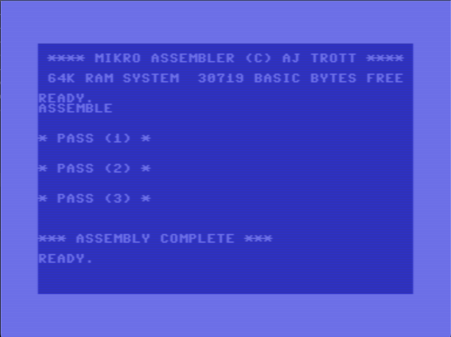
To assemble the code, simply type the command ASSEMBLE. If there are no errors, the code will be assembled and stored at the specified address, $1000.
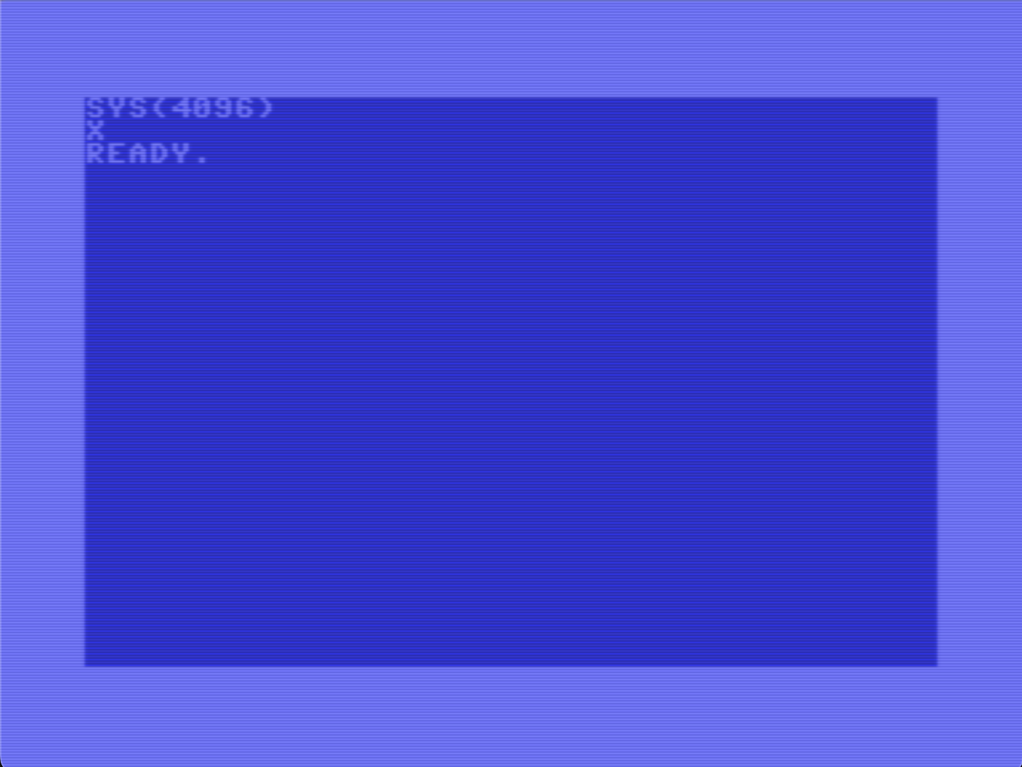
To execute it, use the following BASIC command:
SYS(4096)
When you run it, the code will display an 'X' on the screen and then return to BASIC.
Now, I know what you’re thinking: “That’s not very impressive.” True, the functionality is simple, but here’s the exciting part—this assembler code runs about 1,000 times faster than the equivalent BASIC code. And that’s a speed boost worth getting excited about, don’t you think?
We know now, how to output something on screen, let’s figure out next, how we handle input from the user …
Program 2 - Wait for user input
PRG2.PRG
1 !
2 ! wait char
3 !
5 *=$1000
100 loop jsr $ffe4 ! get char
110 beq loop
999 rts
- Lines 1–5: These lines are identical to the first example.
- Line 100: This line requires a bit more explanation, as it consists of three parts:
loop: This is a label, which acts as a named position in the code that we can jump to without manually calculating memory addresses (a common practice in the 1980s).jsr $ffe4: This calls a built-in function from the C64’s “OS,” known as the Kernal. Specifically, this function retrieves a character from the keyboard. If the keyboard buffer is empty, the value returned in the accumulator (register A) will be 0. Otherwise, it will contain the ASCII code of the pressed key.! get char: This is a comment, similar to the ones in lines 1–3, and is purely for readability.
- Line 110: This line introduces a new mnemonic,
beq, which stands for “Branch if EQual.” If the zero flag contains0(indicating no key press), the program jumps back to thelooplabel. In effect, this creates an endless loop until the user presses a key.
And that’s it! Simple, right? This small program shows how to use a loop and keyboard input to control the program flow—fundamental concepts that we’ll build upon later.
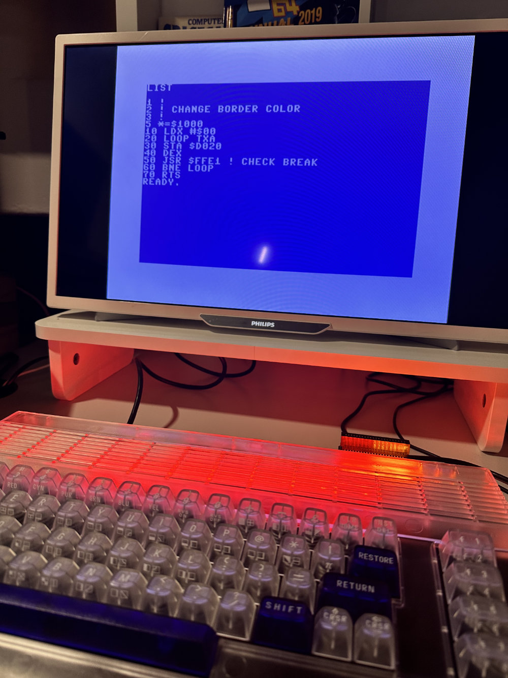
Program 3 - Change border color
PRG3.PRG
1 !
2 ! change border color
3 !
5 *=$1000
100 ldx #$00
110 loop txa
120 sta $d020
130 dex
140 jsr $ffe1 ! check break
150 bne loop
999 rts
This time we do something slightly different, and introduce two new mnemonics and also work with one of the index register the 6502/6510 CPU has: The X-Register. Also we see how we store something from a register to memory instyead of loading (LDA) something.
- Line 100: Similar to LDA we load here a value into the X-register with
LDX #$00. If you wondered before, why we need the ‘#’ sign? This is to describe that we use a constant value to the register (immediate addressing), instead from a memory address. The$marks it as a hex value. Similar to that, we can use%for bijnary numbers and if we use no prefix at all, the assembler understands it as a decimal number. - Line 110 contains again two statements. Again the label loop and then a new mnemonic called TXA. TXA (short for “Transfer X to Accumulator”) is the mnemonic for a machine language instruction which transfers (“copies”) the contents of the X index register into the accumulator.
- Line 120:
sta $d020- At next the value which is now in the Accumulator, will be saved to memory address$d020. This needs some further explanation. The C64 Memory is managed in in different pages, while some of the addresses contain special system information, while others are directly mapped to devices. This is of course a simplification, but helps to understand what happens here actually. This address is mapped to one of the other IC’s in the C64, the VIC chip, and this particular address is responsible for the border color of the screen. So whatever value we store there, it is used by the VIC chip to show one of the available colors on the border of the screen - Line 130:
dexdecrements the value in the X-register - Line 140:
jsr $ffe1is a jump into the ROM again, while this particular function checks the state of the “RUN/STOP” key. If it’s pressed then the Z-Flag will be set. Like this we can stop the program at any time. - Line 150:
bneif the Z-flag is not set (means the STOP key was not pressed), it jumps back to loop and the program continuing changing the border color.
That’s it. Cool effect and a lot of new stuff learned. Still here?
Program 4 - Move the ball
We’ve now explored how to handle user input and display output on the screen. Let’s combine these concepts to lay the foundation for our upcoming game.
PRG4.PRG
1 !
2 ! simple "ball game"
3 !
5 *=$1000
6 !
100 ! setup --------------------------------
101 !
110 lda #$93
120 jsr $ffd2 ! print char
130 ldx #$0c
140 ldy #$1
199 !
200 ! print ball at current pos ------------
201 !
210 start clc
220 jsr $fff0 ! set cursor
230 lda #$71
240 jsr $ffd2 ! print char
299 !
300 ! keyboard input
301 !
310 stx $033c
320 sty $033d
330 loop1 jsr $ffe4 ! getin
340 beq loop1
350 sta $033e
399 !
400 ! clear ball at current pos -------------
401 !
410 ldx $033c
420 ldy $033d
430 clc
440 jsr $fff0 ! set cursor
450 lda #$20
460 jsr $ffd2 ! print char
499 !
500 ! set row and column --------------------
501 !
510 lda $033e
520 cmp #$11 ! check down
530 bne right
540 inx
550 jmp start
560 right cmp #$1d ! check right
570 bne up
580 iny
590 jmp start
600 up cmp #$91 ! check up
610 bne left
620 dex
630 jmp start
640 left cmp #$9d ! check left
650 bne start
660 dey
670 jmp start
999 rts
Although this program is now slightly larger, it’s a good idea to structure it into ‘blocks’ or modules for better organization. Modern cross-platform assemblers would even allow us to separate these into macros or individual files. However, to keep things simple for this tutorial, we’ll keep everything in one file and organize it using line number blocks and clear comments.
- Line 110–140: Setup
- In this section, we print the character
#$93, which is the ASCII code for clearing the screen. We also store the ball’s current position in the X register (row) and the Y register (column).
- In this section, we print the character
- Line 210–240: Print the ball at the current position
- In line 210, we encounter a new mnemonic:
CLC(short for “CLear Carry”), which unconditionally clears the carry flag as preparation for the following call. - The
JSR $FFF0command reads or writes the cursor position, depending on the value of the carry flag. With the carry bit cleared, the cursor moves to the position specified by the X and Y registers. - Finally, we print the ball character using the same ROM call we used in Program 1.
- In line 210, we encounter a new mnemonic:
- Line 310–350: Handle user input
- This section should already feel familiar, as we’ve handled user input before in Program 2. However, there’s one important new concept here: saving and restoring register values. In assembler, ROM calls often modify register values, so you need to save any important data beforehand.
- In this example, we use the addresses
$033C(row),$033D(column), and$033E(key) to temporarily store values. These addresses were originally used by the Tape Recorder (Datasette), which is mostly obsolete today, making them safe for repurposing.
- Line 410–460: Clear the ball at the current position
- Here, we do the opposite of printing the ball. First, we load the saved row and column values back into the X and Y registers. Then, we call the “Set Cursor” function again and print a space character (ASCII 20) to clear the ball from the screen.
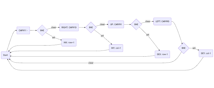
- Line 510–670: Update row and column based on key pressed
- This is the most complex part of the program and may seem intimidating at first because it includes several labels. However, if we break it down step by step, it becomes manageable:
- First, we load the saved key code back into the accumulator.
- In
line 520, we use a new mnemonic:CMP #$11. This compares the value in the accumulator (the saved key code) with the hexadecimal value$11, which corresponds to the Down key. The carry flag is set or cleared depending on the result. - In
line 530, we use theBNE(Branch if Not Equal) mnemonic. If the carry flag was not set, it jumps to the labelright. Otherwise, it increases the X register by 1 (moving the ball down) and jumps back to labelstart. - The other lines follow the same logic for the
Right,Up, andLeftkeys.
- This is the most complex part of the program and may seem intimidating at first because it includes several labels. However, if we break it down step by step, it becomes manageable:
To better visualize this logic, the code block is illustrated in the diagram below.
And that’s it for this part! I hope you’ve enjoyed this section and now have a better understanding of how assembler works on this simple yet iconic CPU. With each step, we’re building the foundation for more complex and exciting programs to come!

What we learned so far
Register and flags used
| Register | Name | Description |
|---|---|---|
| A | Accumulator | The accumulator primarily serves as register for arithmetic and logical operations |
| P | Processor Status Register | The Processor Status Register is a hardware register which records the condition of the CPU as a result of arithmetic, logical or command operations |
| X | X-Register | The X register primarily serves as index register for indexed adressing |
| Y | X-Register | The Y register primarily serves as index register for indexed adressing |
The condition of the 65xx CPUs is recorded by seven combined processor flags and control flags (all within a single byte). Each flag corresponds to a single bit within the Processor Status Register which are explicitly or implicitly read and/or written. The meaning of a bit is either set (1 or true) or cleared (0 or false).
| Flags | Bit | Description |
|---|---|---|
| Zero | 1 | If an operation results in a value of zero, then the flag is set (1). If an operation results in a non-zero value, then the flag is cleared (0) |
Summary of the mnemonics used
| Mnemonic | Description |
|---|---|
| BEQ | BEQ (short for “Branch if EQual”) is the mnemonic for a machine language instruction which branches, or “jumps”, to the address specified if, and only if the zero flag is set. If the zero flag is clear when the CPU encounters a BEQ instruction, the CPU will continue at the instruction following the BEQ rather than taking the jump. |
| BNE | BNE (short for “Branch if Not Equal”) is the mnemonic for a machine language instruction which branches, or “jumps”, to the address specified if, and only if the zero flag is clear. If the zero flag is set when the CPU encounters a BNE instruction, the CPU will continue at the instruction following the BNE rather than taking the jump. |
| CLC | CLC (short for “CLear Carry”) is the mnemonic for a machine language instruction which unconditionally clears the carry flag. |
| CMP | CMP (short for “CoMPare”) is the mnemonic for a machine language instruction which compares the contents of the accumulator against that of the specified operand by subtracting operand from accumulator value, and setting the negative and carry flags according to the result. Unlike SBC, the result of the subtraction is discarded rather than stored back into the accumulator, which is thus unaffected by the CMP operation. |
| DEX | DEX (short for “DEcrease X”) is the mnemonic for a machine language instruction which decrements the numerical value of X index register, by one, and “wraps over” if the value goes below the numerical limits of a byte. |
| DEY | DEY (short for “DEcrease Y”) is the mnemonic for a machine language instruction which decrements the numerical value of Y index register, by one, and “wraps over” if the value goes below the numerical limits of a byte. |
| INX | INX (short for “INcrease X”) is the mnemonic for a machine language instruction which increases the numerical value held in the X index register by one, and “wraps over” when the numerical limits of a byte are exceeded. |
| LDA | LDA (short for “LoaD Accumulator”) is the mnemonic for a machine language instruction which retrieves a copy from the specified RAM or I/O address, and stores it in the accumulator. The content of the memory location is not affected by the operation. |
| LDX | LDX (short for “LoaD X”) is the mnemonic for a machine language instruction which retrieves a copy from the specified RAM or I/O address, and stores it in the X index register. The content of the memory location is not affected by the operation. |
| JSR | JSR (short for “Jump to SubRoutine”) is the mnemonic for a machine language instruction which calls a subroutine. |
| RTS | RTS (short for “ReTurn from Subroutine”) is the mnemonic for a machine language instruction which returns the CPU from a subroutine to the part of the program which initially called the subroutine. |
| STA | STA (short for “STore Accumulator”) is the mnemonic for a machine language instruction which stores a copy of the byte held in the accumulator at the RAM or I/O address specified. The contents of the accumulator itself remains unchanged through the operation. |
| STX | STX (short for “STore X”) is the mnemonic for a machine language instruction which stores a copy of the byte held in the X index register at the RAM or I/O address specified. The contents of the X index register itself remains unchanged through the operation. |
| STY | STY (short for “STore Y”) is the mnemonic for a machine language instruction which stores a copy of the byte held in the Y index register at the RAM or I/O address specified. The contents of the Y index register itself remains unchanged through the operation. |
| TXA | TXA (short for “Transfer X to Accumulator”) is the mnemonic for a machine language instruction which transfers (“copies”) the contents of the X index register into the accumulator. |
Just 15 mnemonics used so far, and we can already achieve a lot with them!
Outlook to Part II: Building a Simple Game in Assembler
Learning assembler programming often feels like solving isolated puzzles—small, focused examples that show specific concepts. While these are useful, they rarely go beyond theory to create something tangible. That’s why, in the next part of this series, I’ll take things further by building a complete, simple game from scratch.
Using the concepts covered in this post—like working with memory, registers, and basic instructions—I’ll create a playable game that runs on the C64. This project will demonstrate how assembler can be used to bring everything together.
Whether you’re a absolute beginner or have dabbled in assembler before, this next step will give you a hands-on, practical example of how to turn theory into something fun and interactive. Stay tuned as I take assembler programming from learning the basics to creating something real and exciting!
Downloads & References
- Source & Assembler
- References
- The 6510 Register Set
- List and description of all available 6502/6510 opcodes
- The C64 ROM
- Memory Map of the C64
- Tools